Satellites, BKG and a bit of fun with Mr Yagi and Mr Uda
How it started
About two years ago, I fell under the spell of Morse code. As for speed, I can now manage about 15 WPM in normal conversation, and when it comes to contest-style operating and FloraFauna and POTA activations (which are my favourite activities), I can pick up about 20–25 WPM when reading call signs. Not exactly stellar results, but it’s enough for me to enjoy my outdoor CW activations.
As the biggest challenge in telegraphy is receiving rather than transmitting, I practise transmitting practically only when I’m on the band. As for receiving, my training mainly consists of watching YouTube videos of other operators’ POTA, SOTA and similar activations in my spare moments – for example, whilst cooking or on solo walks outdoors – or listening to Andy Weir’s book The Martian in Morse code. The more I listen to this, the more YouTube naturally suggests related content, which is how Forrest’s channel, KI7QCF caught my attention. Forrest is an American who has dedicated his YouTube channel to promoting telegraphy (CW), and I’d say he’s doing quite well at it.
Brass Knuckle Gang
Among other things, Forrest set up something called the Brass Knuckle Gang (BKG)
- It’s a bit of a fun club that brings together telegraph operators working on 2m, because the barrier to entry for 2m CW these days is, for example, just the Chinese Quansheng handheld – both loved and hated – with modified firmware; so there’s no need for any super-sophisticated, and therefore expensive, equipment, as was the case in the past. Anyone can become a member of the BKG by successfully making contact with an existing BKG operator on 2m, or via satellite – using CW mode, of course.
Besides watching (or rather listening to) Forrest’s videos, I follow Thomas K4SWL’s YouTube channel where he films practically all his outdoor activations – POTA, SOTA, etc. – and he also has a website QRPer.com where, next to his own articles, he also publishes articles from others. And thanks to that, I came across this article by Josh VE3YTX.
Josh is a novice amateur radio operator who describes in his article how he’s exploring various aspects of the HAM hobby. As he wanted to become a member of the BKG, he looked at the membership map on the BKG website to find out where the nearest member was located so that he could join, too. However, he discovered that nearest member was about 200 miles away, making contact on 2 metres impossible for him. So, on the BKG’s Discord, he was advised that he could try to work somebody using a satellite. As he’d never heard of satellite operations before, he set about finding out how it actually works, and once he’d studied the basics, he immediately set about building a Yagi-Uda antenna for satellite operations. In the end, it all worked out well and he now has his own BKG membership number too. But the reason I’m writing all this is that it inspired me to try satellite operations (and perhaps become a BKG member myself sometime) as well.
Antenna build
To begin with, I needed to build an antenna. So I searched the internet for a good set of instructions for a simple, DIY-friendly and, ideally, easily dismantlable antenna for satellite use. I found a very well-written antenna build instructions by IK3ITB and decided to follow it. I’ve got the tools, and I’m quite handy, too, so off I went to buy the materials. The guide calls for 4mm aluminium rods (which could be, for example, aluminium welding wires). As I wanted to capitalise on my momentum and enthusiasm, I immediately looked for a local supplier of welding equipment, but they only sold whole packs of welding rods, each containing around a hundred pieces. What’s more, they’re normally 1000mm long, but the longest component in the guide is 1020mm, so what is sold isn’t long enough. So I wondered where I could buy something similar, and I thought I’d seen some aluminium rods and tubes at the local DIY hardware store some time ago. I worked out the total length I needed for all the components and went shopping.
They didn’t have any 4mm aluminium rods, so I bought a 6mm anodised aluminium tube. At an electrical supplies shop, I bought a 25mm round protective conduit, clips for it and boxes to house the dipoles (radiating elements). I also had to order some RG316 coaxial cable online, which will be used inside the boxes to wind the chokes, and then I started the build. For the most part, I followed the instructions, but as it’s a top priority for me that the antenna can be dismantled (as it’s easier to store and carry, in case I want to operate satellites outdoors and the antenna fits in a backpack, for example), I made certain modifications during the build.
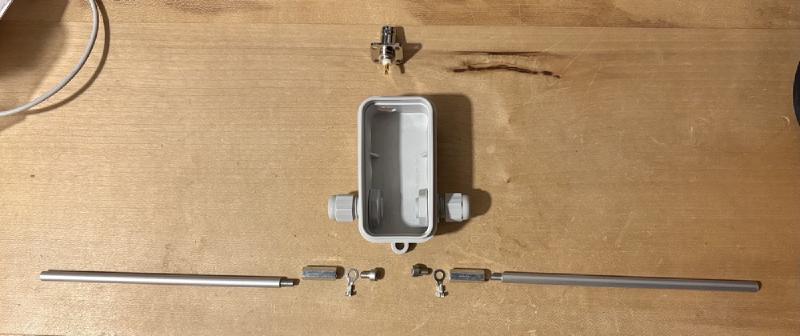
In the version described in the original instructions, the radiating elements are permanently attached to the boom, which means that the dipole on the boom would always stick out and take up space. I wanted the dipole to be removable as well, so I screwed an M4 metric bolt onto the end of the tube. The hole was just the right diameter and, with a bit of force, the M4 bolt screwed into the aluminium quite nicely and securely. I then cut off the head of the bolt. Inside the box for the dipole, I placed an M4x20 extension nut into which the radiating element is then screwed. This meant that I could also remove the dipole’s radiating elements, and the boom is essentially just a tube with boxes for the dipoles, with nothing sticking out to the sides. Brilliant.
As I was curious about how a Yagi-Uda antenna works, I fed the instructions to a language model (these days it’s fashionable to call it AI, or ‘artificial intelligence’). It patiently explained it to me, whilst also pointing out that, according to the instructions, the choke for the VHF band had too few turns; it advised me and worked out how many I should wind on for optimal performance. As I’m no antenna expert, I decided to trust it and give it a go. At the same time, whilst explaining the theory, it mentioned, just by the way, that the thickness of the elements is also important for tuning the antenna. It hadn’t occurred to me to think about that, but it actually makes sense, because if I took it to the extreme and used tubes with a diameter of, say, 10 cm, it would certainly alter the antenna’s geometry. As it hadn’t occurred to me that this could be a problem, I simply bought and used the diameter of elements that I was able to get hold of. So I went to ask what effect changing from 4 mm to 6 mm would have. As I’d already cut the elements to precise lengths, I was worried about what the answer would be, because it might turn out that they’d be too short and I’d have to redo all the elements – even though I’d already attached them and secured them with clips.
The recommendation was that I should shorten all the elements, not the reflector though, by one to two mm. As such a change in length is not very significant, AI advised me to measure the antenna first using VNA, as there was a chance that nothing would need to be shortened. After three long days of waiting for the RG316 coaxial cable to wind the chokes, I wound the coils as soon as the cable arrived and went taking the measurements using the nanoVNA.
UHF section
I started with the UHF portion of the antenna. However, once I connected it, I was surprised by a rather nonsensical pattern on the Smith chart and an SWR of around 1:8. It struck me as very odd that a difference of two millimetres in the thickness of the elements should cause such a dramatic jump in the standing wave ratio. The multimeter didn’t indicate a short circuit between the two halves of the dipole, so I went back to Gemini to have a moan. The reply was something along the lines of: ‘Your intuition is correct; such a small difference in element thickness can’t cause an SWR like that – you’ve got something wrong. Here’s a list of likely faults, so go and have a look – good luck.’
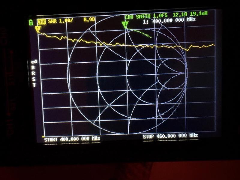
Fortunately, the search didn’t take long. It turned out that the live (centre) conductor at the BNC connector inside the choke box had probably become broken whilst I was handling it. Visually, it looked as it was correctly soldered in place, but when I tried wiggling it with a pair of tweezers, it turned out the wire was snapped and that it was just hanging in the air. The repair took just a moment; I reconnected the VNA and this was the result:
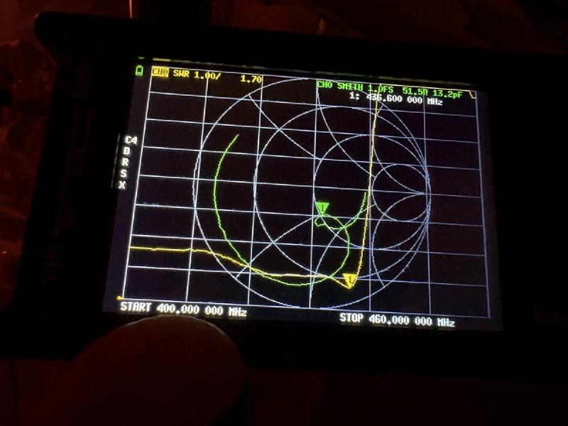
At first glance, it looks quite good, but that dip (peak) on the right is roughly in the middle of the UHF band, not above it, so it needed to be shifted up to above 440 MHz. Incidentally, that’s exactly what the simulation model warned me about – that using thicker elements would shift the frequency downwards and it would probably be necessary to shorten the radiator and reflectors. I asked by how much, and was told that shortening them by about 1 mm on each side would shift the frequency up by about 5 MHz. So I removed the elements from the boom, measured out 1 mm with a calliper and filed them down in a vice. Quite a tedious little job. Full of anticipation, I snapped the elements back onto the boom and went to measure again.
The simulation model wasn’t lying – the frequency had shifted, but only by about 1.5 MHz, so that was a bit of a let-down. As I had three different coaxial cables of varying lengths (15 cm, 30 cm and 2 m) for connecting the VNA to the antenna, just out of curiosity I tried using all three cables, one after another, to connect the VNA to the antenna, and each time I got different results. That gave me pause for thought. I went to ask how this could be possible. I learnt that, apparently, with every lambda/4 length of cable, everything is reversed (low impedance becomes high impedance and capacitance becomes inductance). And because I’d calibrated the VNA without a cable connected, I was actually measuring not only the antenna but also the cable itself, which was ‘skewing’ my results. The solution was to calibrate the VNA with the connecting cable – the one I’d use to connect to the antenna – attached, thereby compensating for the cable’s effect. So I calibrated the VNA and had another round of measurement.
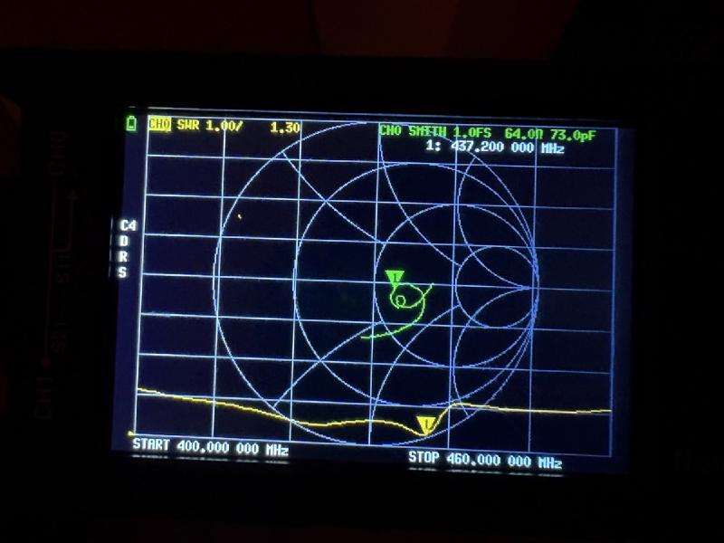
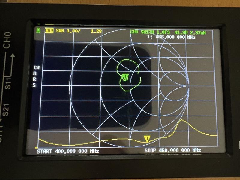
After calibration, a lot changed: the SWR at the ‘lowest point’ dropped from 1:1.7 to 1:1.3, whilst the sharp rise in SWR after the ‘cutoff frequency’ became a much smaller bump than it had been before calibration. However, the break frequency remained unchanged and was still just above the centre of the UHF HAM band, so I needed to adjust it further; I was told to remove another 2 mm from all elements except the reflector. So I went about another round of fine-tuning, element by element. In terms of the frequency shift, almost nothing happened again, and at the same time, the SWR dip beyond the break point worsened.
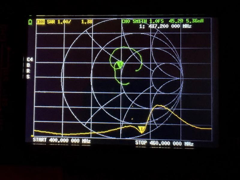
After another round of consultations with Gemini, I was advised to remove a further 4 mm (2 mm from each side). That was too much to tackle with a file, so I used a hacksaw. I’d been advised not to remove the full 4 mm in one go, but to do it gradually. However, I was starting to get a bit fed up with doing it bit by bit, so I removed 1.75 mm from both sides of all the elements.
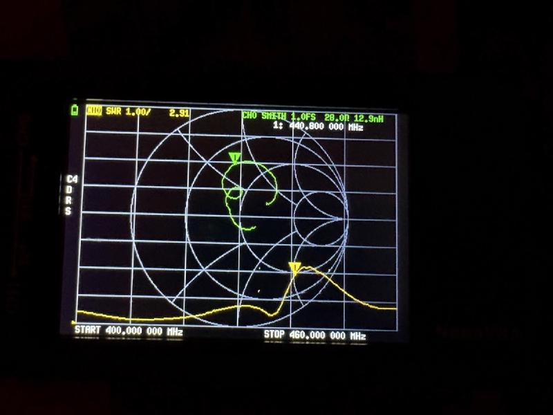
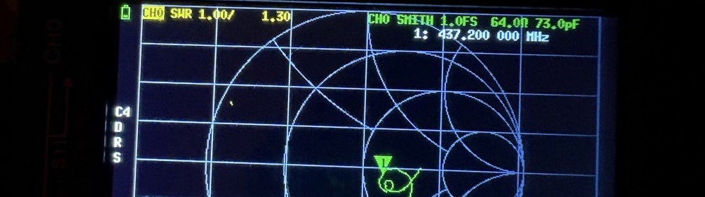
I was finally starting to get where I wanted to be – the cut-off frequency had shifted slightly above 440 MHz, but the VNA was still showing too much inductance. The advice from the language model was to keep the unshielded coaxial cable connections within the box with the choke as short as possible – simply keep the stripped sections as short as possible, because apparently this then behaves like a series choke and messes things up (especially in the UHF band – the higher the frequency, the worse this phenomenon gets). So, following this advice, I shortened all the internal connections as much as possible. And it actually helped a little. One last thing didn’t sit right with me – Gemini hadn’t asked me to shorten the reflector at all, but when I pointed out to him that it seemed odd to me, given that the yagi-uda elements interact with one another, he conceded that I should also shorten the reflector proportionally, which I did. In the end, I settled on an average SWR of 1:1.4 for the UHF section of the antenna and told myself that was good enough and that I wouldn’t tinker with it any further, so as not to make things worse, especially as I know nothing about yagi design. On the graph, the final result on UHF part of the antenna looked something like this:
VHF section
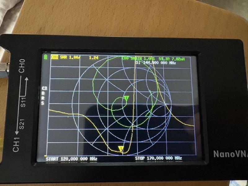
Fortunately, the story behind the VHF section of the antenna is very brief – everything looked fine on the first attempt and nothing needed changing; even the SWR is very good.
How does it look?
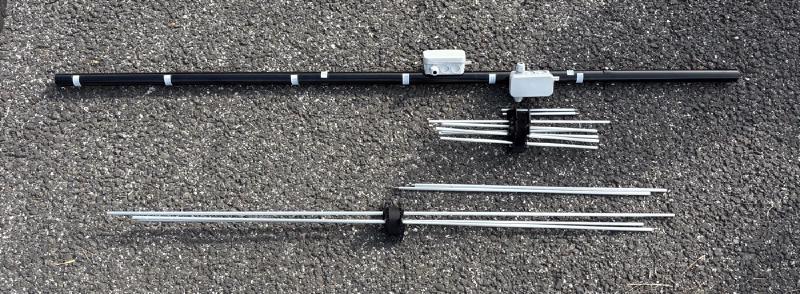
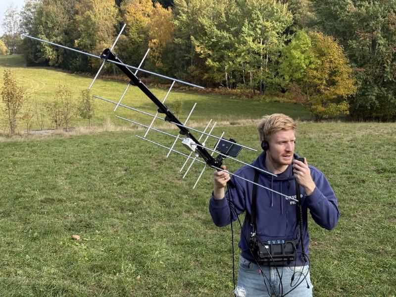
Here are the photos of the antenna - disassembled and assembled.
What next?
The antenna is built, it looks good and seems to be tuned properly. I built it over the course of about a week, working on it in the evenings and in spare moments. Next time, I’d use sturdier boxes to house the chokes, because the electrical boxes I’ve used there do the job, but they warp a bit as they aren’t made of rigid plastic. Another lesson I’ve learnt is – calibrate your VNA, including the connecting cable, otherwise you’ll get inaccurate results. I also learnt a little bit more about the Yagi-Uda antenna. Not much, but at least a bit. I can’t say whether Gemini was pulling my leg or not, but when explaining things he was throwing maths on me and sounded convincing (mind you, language models are good at that – sounding convincing even when they’re making things up or outright lying).
Well, the final SWR looked usable on both bands. I certainly wouldn’t want to present my documented procedure as a guide. I wanted more to show in detail how I went about it – perhaps even badly, but that’s what HAM radio is all about: experiments that don’t always end in success first time round. Fortunately, it turned out well in this case. I’ll maybe write about how the antenna performs in actual operation once I’ve tested it in real satellite traffic (which I still don’t know much about).
What about BKG – shall I become a member? I’m not sure yet; maybe, perhaps via that satellite one day, but the fact is that VE3YTX’s article was my gateway to taking an interest in satellites and trying something new again. I’m still fascinated by all the things you can do in the world of amateur radio. If you’ve grown tired of the activities you’ve been doing so far, try a new mode, build a new antenna or piece of kit, or give a new activity a go that will be a challenge for you. Fortunately, I haven’t grown tired of my current activities on shortwave and Morse code just yet, and adding something else to my arsenal of experiences is great!
Hail to learning, experimenting and pushing the boundaries!